
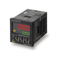
TECHOMETER 48 × 48MM SOCKET TYPE H7CX-R11D1-N OMRON
KSh36,899.00
TECHOMETER 48 × 48MM SOCKET TYPE H7CX-R11D1-N OMRON
TECHOMETER 48 × 48MM SOCKET TYPE H7CX-R11D1-N OMRON
Description;NTECHOMETER 48 × 48MM SOCKET TYPE H7CX-R11D1-N OMRO
| Classification | Tachometer | Model | H7CX-R11[]-N | H7CX-R11W[]-N | Input mode | 1 input only | 2 inputs only | Ratings | Power supply | ||||||||||||||||||||||||||||||||||||||||||||||||||||||||||||
|---|---|---|---|---|---|---|---|---|---|---|---|---|---|---|---|---|---|---|---|---|---|---|---|---|---|---|---|---|---|---|---|---|---|---|---|---|---|---|---|---|---|---|---|---|---|---|---|---|---|---|---|---|---|---|---|---|---|---|---|---|---|---|---|---|---|---|---|---|---|
| 12 to 24 VDC or 24 VAC, 50/60 Hz | Operating voltage | ||||||||||||||||||||||||||||||||||||||||||||||||||||||||||||||||||||
| fluctuation range | 85% to 110% of rated supply voltage (90% to 110% at 12 to 24 VDC) | Power | |||||||||||||||||||||||||||||||||||||||||||||||||||||||||||||||||||
consumption | Approx. 9.4 VA at 100 to 240 VAC, Approx. 7.2 VA/4.7 W at 24 VAC/12 to 24 VDC, Approx. 3.7 W at | 12 to 24 VDC | Mounting method | Flush mounting or surface mounting | External connections | 11-pin socket | Degree of protection | IEC IP66, UL508 Type 4 (indoors) for panel surface only and when Y92S-29 Waterproof Packing is used | Input signals | Count and hold | Count 1 and count 2 | Pulse measurement method | Tachometer mode | ||||||||||||||||||||||||||||||||||||||||||||||||||||||||
| (cycle measurement) | Maximum counting speed | 30 Hz | |||||||||||||||||||||||||||||||||||||||||||||||||||||||||||||||||||
| (minimum pulse | (minimum pulse |
width: 16.7 ms) or 5 kHz (minimum pulse width: 0.1 ms) | |||||||||||||||||||||||||||||||||||||||||||||||||||||||||||||||||||
| (selectable) | Minimum input signal width | — | 10 ms | 1 ms | — | Measuring ranges | 0.001 Hz to 30.00Hz | 0.001 Hz to 10 kHz | 0.026 to 999999 s | 0.003 to 999999 s | 0.01 to 5k Hz | Sampling cycle | 200 ms min. | ||||||||||||||||||||||||||||||||||||||||||||||||||||||||
| Continuous measurement | |||||||||||||||||||||||||||||||||||||||||||||||||||||||||||||||||||||
|
Averaging not used: 200 ms Averaging used: 200 multiplied by the averaging setting (ms) Input pulse of less than 5 Hz Averaging not used: Two times the maximum input pulse cycle Using averaging: Two times the maximum of the input pulse cycle multiplied by the averaging setting. | |||||||||||||||||||||||||||||||||||||||||||||||||||||||||||||||||||||
| (at 23 ±5°C) | Output mode | HI-LO, AREA, HI-HI, LO-LO | HI-HI, LO-LO | Auto-zero time | 0.1 to 999.9 s (in Tachometer Mode) | Startup time | 0.0 to 99.9 s | Averaging | Simple averaging/moving averaging selectable, Number of times: OFF, 2, 4, or 8 times | Prescaling function | 0.001 to 99.999 (in Tachometer Mode) | Decimal point adjustment | Rightmost 3 digits | — | Sensor waiting time | 290 ms max. | |||||||||||||||||||||||||||||||||||||||||||||||||||||
| (Control output is turned OFF and no input is accepted during sensor waiting time.) | |||||||||||||||||||||||||||||||||||||||||||||||||||||||||||||||||||||
|
No-voltage Input Impedance when ON: 1 kΩ max. (Leakage current: 12 mA when 0 Ω) ON residual voltage: 3 V max. Impedance when OFF: 100 kΩ min. Voltage Input High (logic) level: 4.5 to 30 VDC Low (logic) level: 0 to 2 VDC (Input resistance: approx. | |||||||||||||||||||||||||||||||||||||||||||||||||||||||||||||||||||||
| 4.7 kΩ) | Hold input | Minimum input signal width: 20 ms | — | External power supply | 12 VDC (±10%), 100 mA | ||||||||||||||||||||||||||||||||||||||||||||||||||||||||||||||||
| * Refer to Safety Precautions (Common) on Data Sheet for details. | |||||||||||||||||||||||||||||||||||||||||||||||||||||||||||||||||||||
| Minimum applied load:10 mA at 5 VDC (failure level: P, reference value) | Display *2 | 7-segment, negative transmissive LCD | |||||||||||||||||||||||||||||||||||||||||||||||||||||||||||||||||||
| Character height | |||||||||||||||||||||||||||||||||||||||||||||||||||||||||||||||||||||
| Present value: 10 mm (red), comparison value: 6 mm (green) | Digits | 6 digits (0 to 999999) | Memory backup | EEPROM (overwrites: 100,000 times min.) that can store data for 10 years min. | |||||||||||||||||||||||||||||||||||||||||||||||||||||||||||||||||
| Operating temperature | range | -10 to 55°C (-10 to 50°C if Counter/Tachometers are mounted side by side) (with no icing or condensation) | Storage temperature range | -25 to 70°C (with no icing or condensation) | Operating humidity range | 25% to 85% | Case color | Black (N1.5) | |||||||||||||||||||||||||||||||||||||||||||||||||||||||||||||
*1. Do not use the output from an inverter as the power supply. The ripple must be 20% maximum for CC power.
*2. The display is lit only when the power is ON. Nothing is displayed when power is OFF.
Characteristics
| (at 500 VDC) between current-carrying terminal and exposed non-current-carrying metal parts, and between non-continuous contacts | Dielectric strength | 2,000 VAC, 50/60 Hz for 1 min between current-carrying metal parts and non-current-carrying metal parts | |||||||||||||||||||||||||||
|---|---|---|---|---|---|---|---|---|---|---|---|---|---|---|---|---|---|---|---|---|---|---|---|---|---|---|---|---|---|
|
2,000 VAC (for 100 to 240 VAC), 50/60 Hz for 1 min between power supply and input circuit (1,000 VAC for 24 VAC/12 to 24 VDC) 2,000 VAC 50/60 Hz for 1 min between control output, power supply, and input circuit | |||||||||||||||||||||||||||||
| 1,000 VAC, 50/60 Hz for 1 min between non-continuous contacts | Impulse withstand voltage | 3.0 kV (between power terminals) for 100 to 240 VAC, 1.0 kV for 24 VAC/12 to 24 VDC | |||||||||||||||||||||||||||
| 4.5 kV (between current-carrying terminal and exposed non-current-carrying metal parts) for 100 to 240 VAC, 1.5 kV for 24 VAC/12 to 24 VDC | Noise immunity | ±1.5 kV (between power terminals) | |||||||||||||||||||||||||||
| ±600 V (between input terminals) | |||||||||||||||||||||||||||||
| Square-wave noise by noise simulator (pulse width: 100 ns/1 μs, 1-ns rise) | Static immunity | Destruction: 15 kV, Malfunction: 8 kV | Vibration | ||||||||||||||||||||||||||
| resistance | Destruction | 10 to 55 Hz with 0.75-mm single amplitude, each in three directions for 2 hours | Malfunction | 10 to 55 Hz with 0.35-mm single amplitude, each in three directions for 10 min | Shock | ||||||||||||||||||||||||
| re-sistance | Destruction | 300m/s2 each in three directions, three cycles | Malfunction | 100m/s2 each in three directions, three cycles | Life expectancy | Mechanical: 10,000,000 operations min. | |||||||||||||||||||||||
| Electrical: 100,000 operations min. | |||||||||||||||||||||||||||||
| (3 A at 250 VAC, resistive load, ambient temperature condition: 23°C) * | Weight | Approx. | |||||||||||||||||||||||||||
| 110 g (Tachometer only) | |||||||||||||||||||||||||||||
* See Life-test Curve (Reference Values).
Life-test Curve (Reference Values)
Resistive Load

Inductive Load
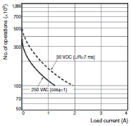
A current of 0.15 A max. can be switched at 125 VDC (cosφ=1) (Life expectancy: 100,000 operations)
A current of 0.1 A max. can be switched if L/R=7 ms.
(Life expectancy: 100,000 operations)
Applicable Standards
| Approved safety | Conforms to EN 61010-1 (IEC 61010-1): Pollution degree 2/overvoltage category II, B300 PILOT DUTY, | ||||||||||||||||||
|---|---|---|---|---|---|---|---|---|---|---|---|---|---|---|---|---|---|---|---|
| 1/4 HP 120 VAC, 1/3 HP, 240 VAC, 3-A resistive load | EMC | (EMI) EN61326-1 *2 | |||||||||||||||||
|
Emission Enclosure: EN55011 Group 1 classA Emission AC mains: EN55011 Group 1 classA (EMS) EN61326-1 *2 Immunity ESD: EN61000-4-2: 4 kV contact discharge (level 2); 8 kV air discharge (level 3) Immunity RF-interference: EN61000-4-3: 10 V/m (Amplitude-modulated, 80 MHz to 1 GHz) (level 3); 10 V/m (Pulse-modulated, 900 MHz ±5 MHz) (level 3) Immunity Conducted Disturbance: EN61000-4-6: 10 V (0.15 to 80 MHz) (level 3) Immunity Burst: EN61000-4-4: 2 kV power-line (level 3); 1 kV I/O signal-line (level 4) Immunity Surge: EN61000-4-5: 1 kV line to lines (power and output lines) (level 2); 2 kV line to ground (power and output lines) (level 3) Immunity Voltage Dip/Interruption: EN61000-4-11: 0.5 cycle, 100% (rated voltage) |
*1. The following safety standards apply to the H7CX-R11[].
cUL (Listing): Applicable when an OMRON P2CF(-E) Socket is used.
cUR (Recognition): Applicable when any other socket is used.
*2. Industrial electromagnetic environment (EN/IEC 61326-1 Table 2)
I/O Functions
| The hold indicator is lit during hold. * | Outputs | OUT | Outputs signals according to the specified output mode when a comparison | ||||||||||||||||
|---|---|---|---|---|---|---|---|---|---|---|---|---|---|---|---|---|---|---|---|
| value is reached. |
* Refer to Data Sheet for details on the hold function.
The following table shows the delay from when the reset signal is input until the output is turned OFF. (Reference values)
| Minimum reset signal width | Output delay time | 1 ms | 0.8 to 1.2 ms | 20 ms | 15 to 25 ms |
|---|
Related products

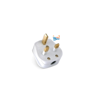
Powermax Top Plug 13a
KSh130.00Add to cartPowermax Top Plug 13a WSG-49725 Description; The 13A plug is designed to be used with 230-volt AC power outlets. It is a very safe plug, as it has a number of safety features built in. For example, the plug has a shutter that covers the live pins when the plug is not in use. The …
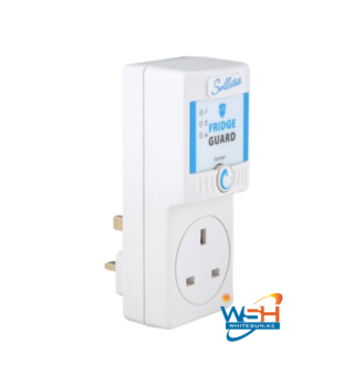
FRIDGE/FREEZER GUARD
Original price was: KSh900.00.KSh550.00Current price is: KSh550.00.
Reviews
There are no reviews yet.